As part of Cal Poly’s ME 443 Hydropower Contest, our team designed and built a Pelton wheel-based hydraulic system to convert potential energy from a 1-liter water reservoir into mechanical energy capable of pulling a 1-newton sled over 20 feet. The system was constrained by competition rules, including a max reservoir height of 65 inches, 6 meters of 3/8-inch tubing, and a 6-inch turbine diameter. The main engineering challenge was to optimize efficiency within these limits while ensuring practical performance during two competitive trials.
__________________________________________________________________________________________
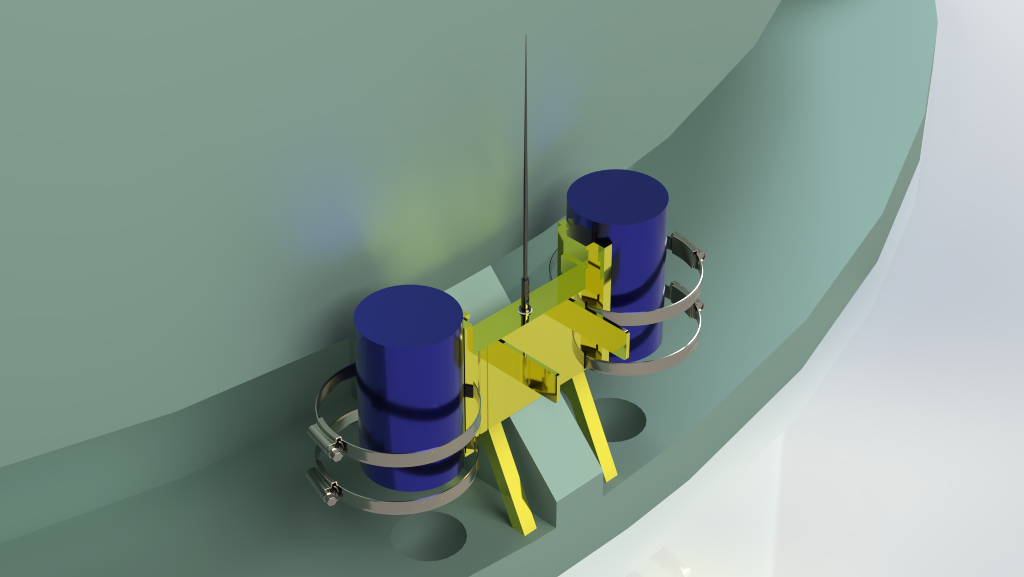
To maximize the water volume stored in our system while staying within design constraints, we opted to use three strands of 3/8-inch tubing. This configuration allowed us to reach the reservoir’s maximum allowable weight and still utilize approximately 80% of the total tubing available. Shown on the left is our custom manifold, which merges the three flow paths into a single stream and turns it horizontal before it enters the nozzle. Adjacent to that is our reservoir, purposefully designed to promote smooth water distribution into the three tubes. Because there is no abrupt change in diameter at the outlet and the intake transitions are gradual, minor losses at the junctions are minimized. This same design was carried through into the 3-to-1 manifold to ensure consistent and efficient flow. All surfaces that come into contact with water were sprayed with a high-gloss paint to reduce losses from surface tension and reduce surface imperfections.
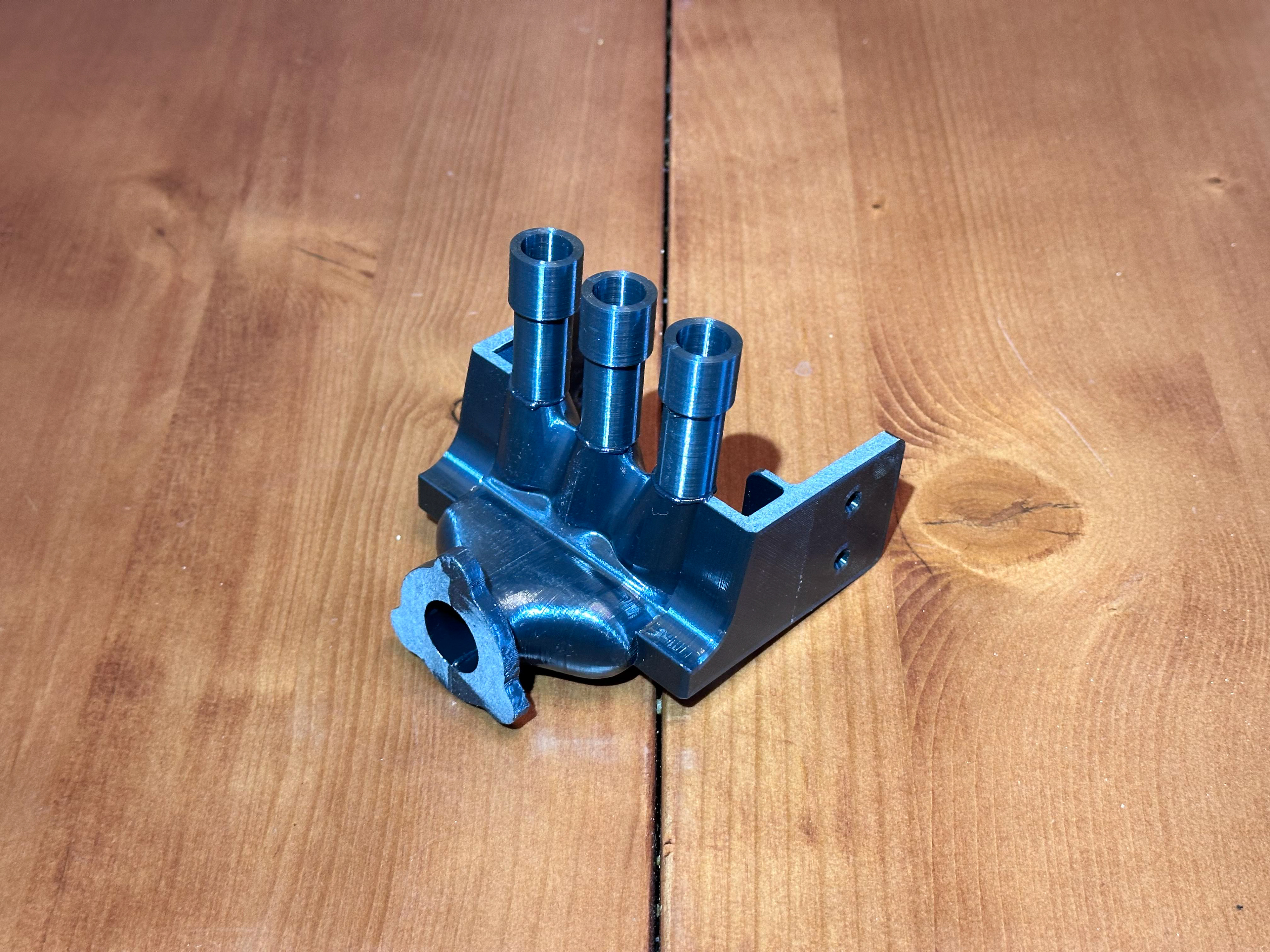
3-1 manifold
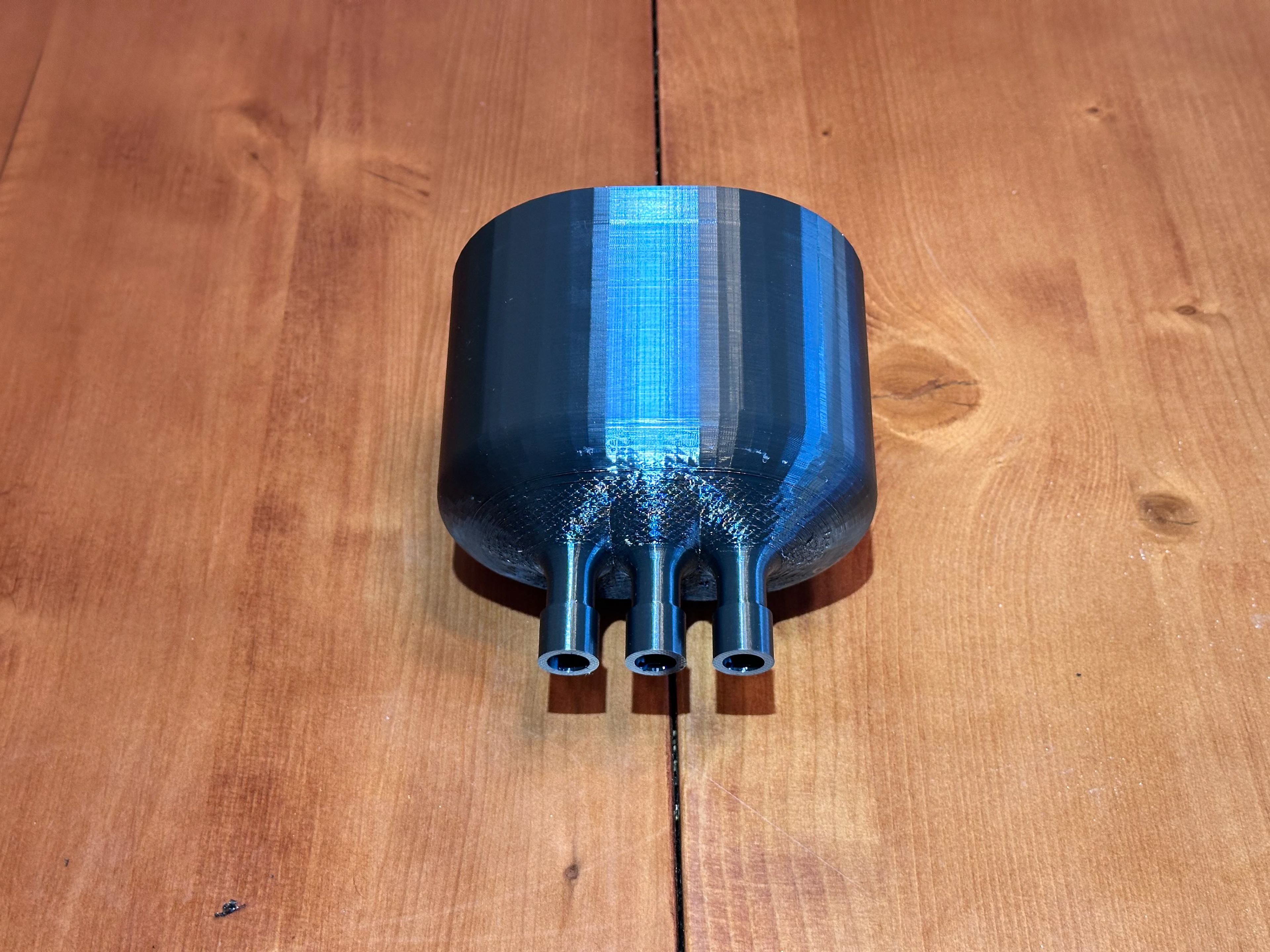
Water reservoir
Using Excel and Engineering Equation Solver (EES), we conducted detailed fluid dynamics analyses. Bernoulli’s equation and energy conservation principles were applied to identify the optimal nozzle diameter, accounting for frictional losses using the Colebrook model. A parametric study determined the ideal nozzle size to be 0.39 inches, balancing mass flow and head loss. Based on this, a Pelton wheel efficiency of 75% was assumed to calculate pulley sizes and performance. Final design constraints led to a 7.5-inch maximum pulley diameter due to axle height limitations, despite a theoretical optimum of 12.8 inches.
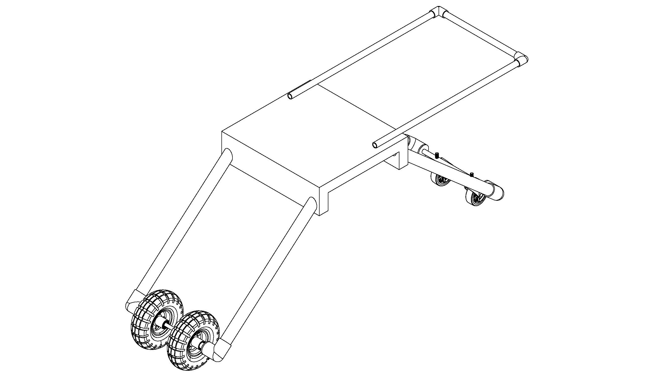
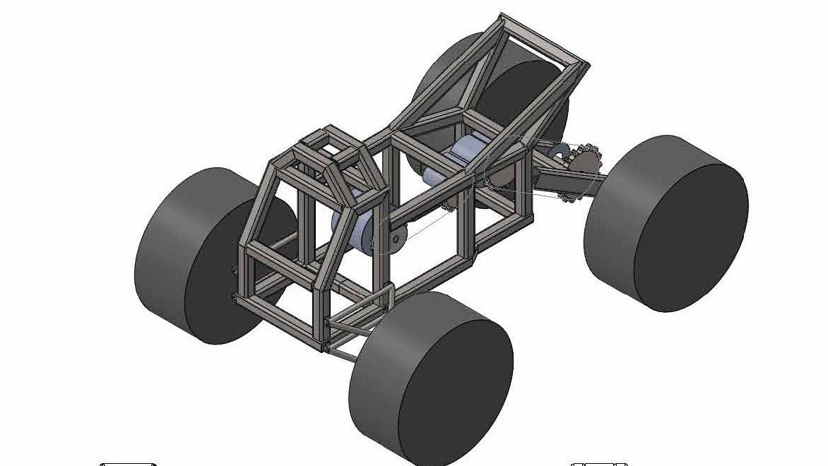
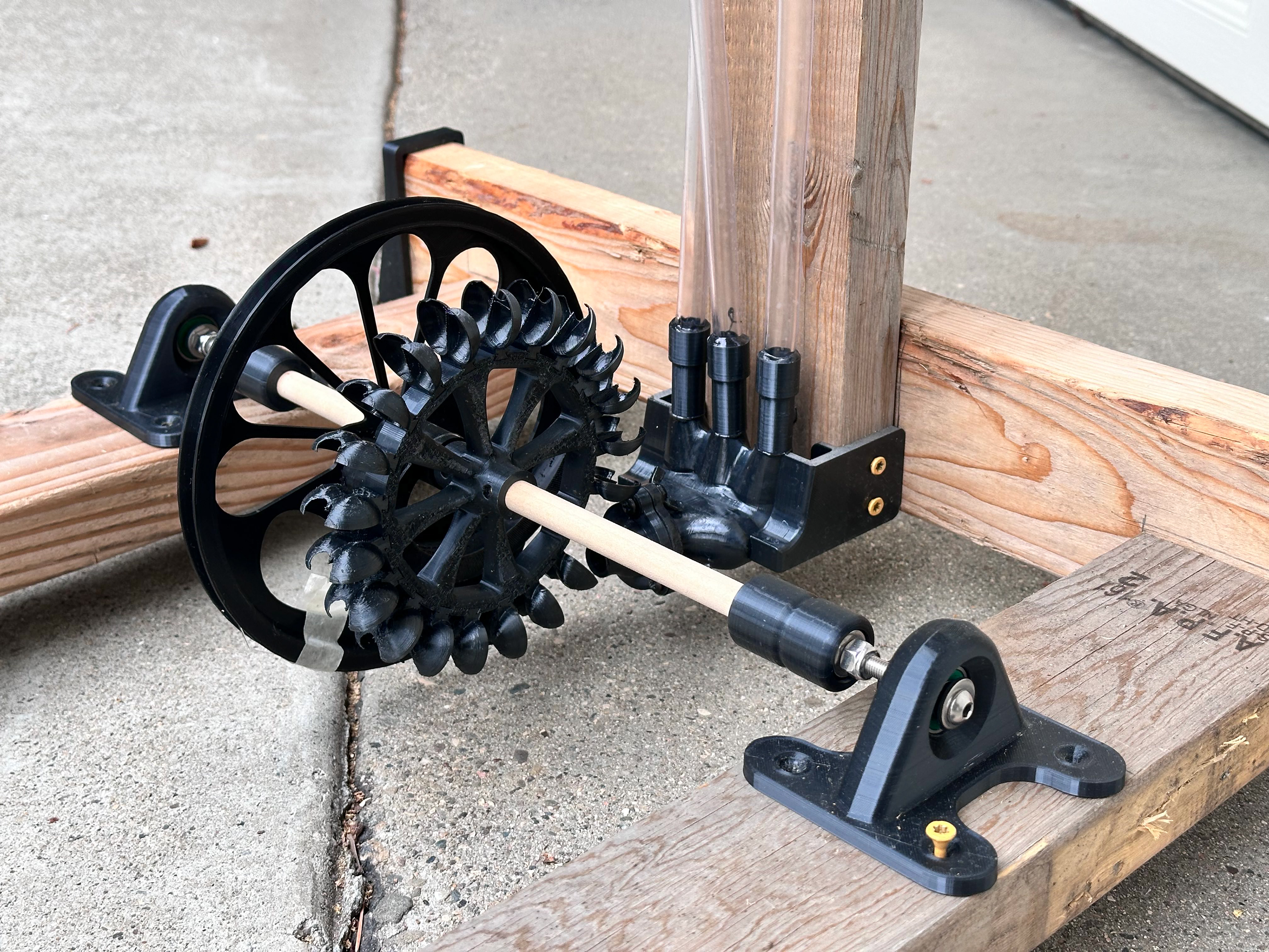
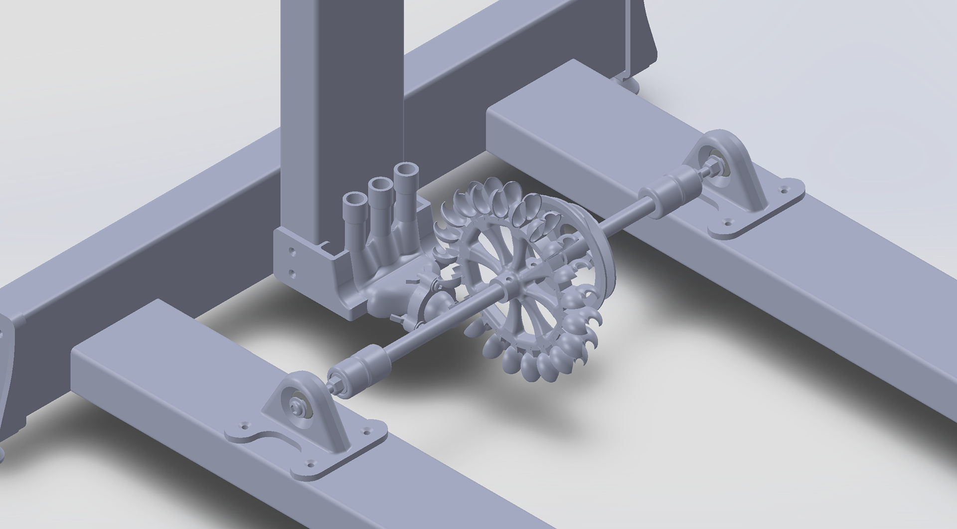
The Pelton wheel had 21 custom 3D-printed buckets mounted on a dovetail, designed with a 5.15-inch pitch diameter and optimized entry and exit angles (20° and 6° respectively). A wooden axle supported variable-diameter pulleys that were intended to reduce startup resistance and improve acceleration. The full system was built on a modular 2x4 wooden frame with adjustable leveling feet for outdoor testing. Below is an in-depth view of the assembled Pelton turbine, the pulley, and the nozzle.
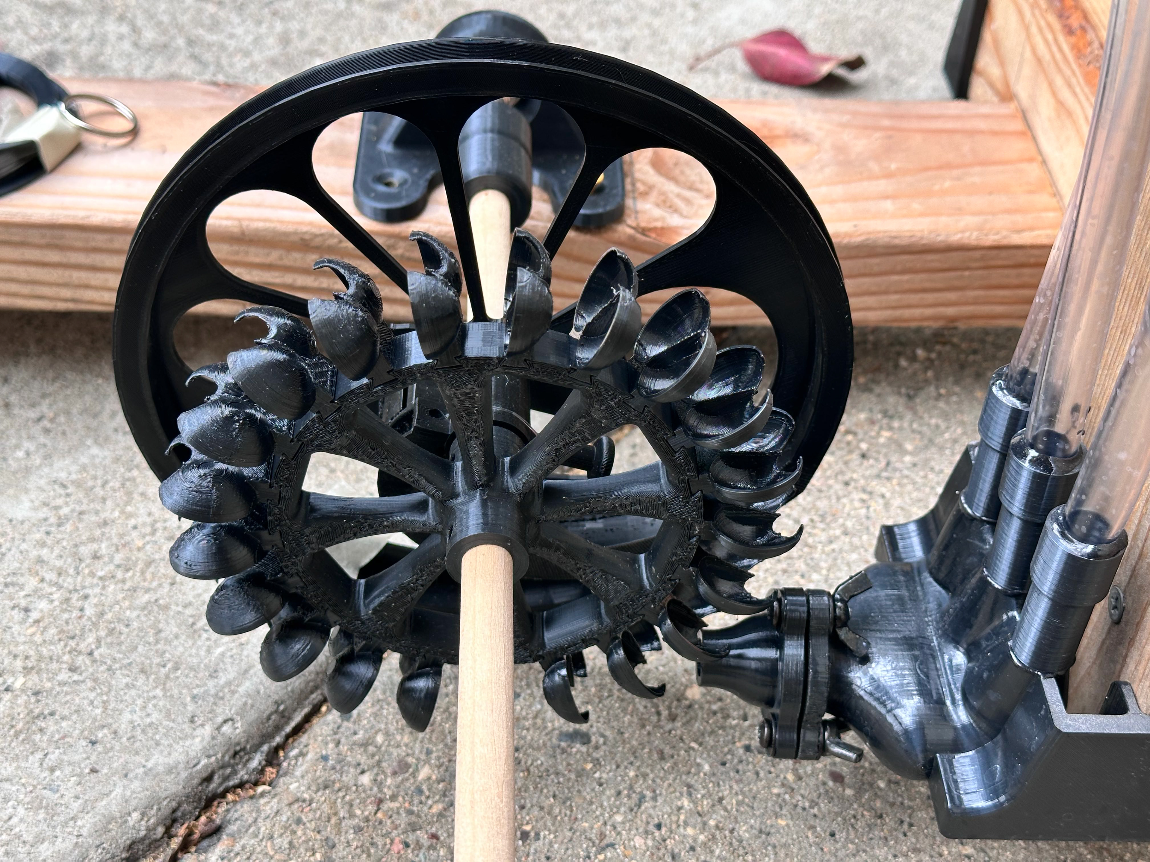
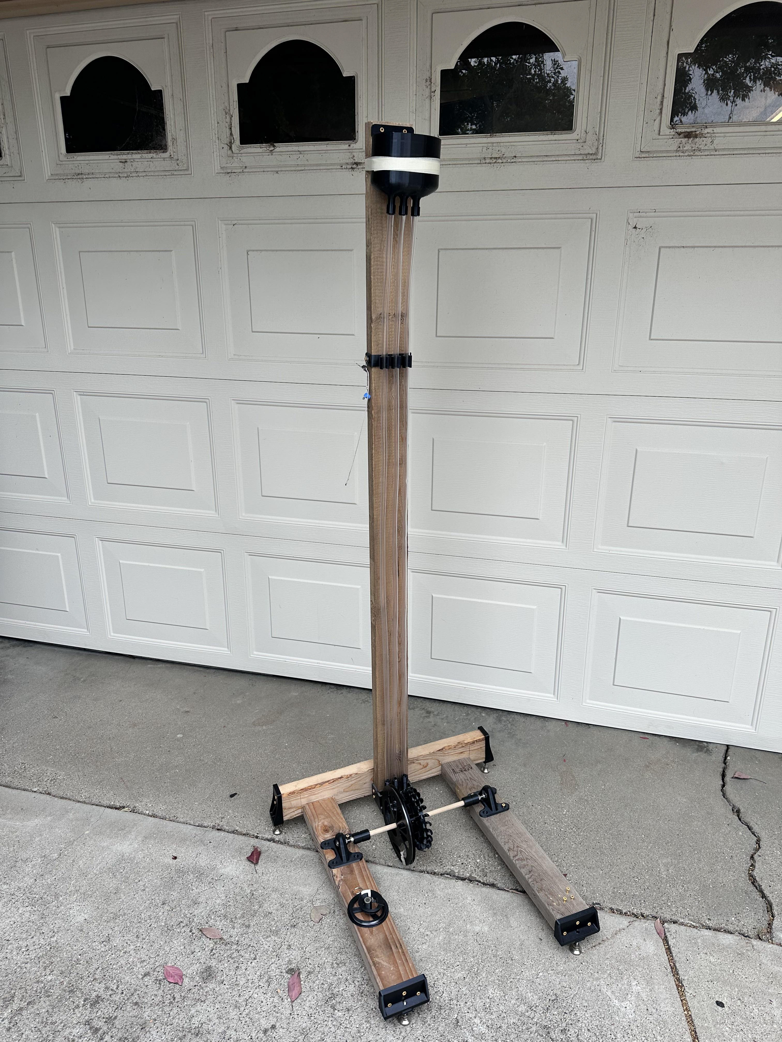
Here is our complete design.
Below is a video from our first trial run. Due to an initial miscalculation, the pulley was undersized at 4 inches because we mistakenly assumed the sled weighed 1 pound instead of 1 newton. While the system successfully pulled the weight in approximately 4 seconds, the turbine performance was clearly suboptimal. This was evident in the water’s behavior after exiting the Pelton buckets, as it continued moving in the same direction as the incoming jet. In an ideal scenario, a properly loaded Pelton bucket should fully redirect the flow at steady state. The lack of sufficient load caused by the small pulley led to this inefficiency, which prompted us to revise our calculations using the corrected weight.
After correcting the weight in our calculations, we determined that the optimal pulley diameter was 12.8 inches. However, due to the size constraints of our 3D printer and our axle height, we were limited to producing a maximum pulley size of 7.5 inches. In the video below, the updated pulley has been installed. With this adjustment, the Pelton wheel operates much more efficiently. The water is now fully redirected upon exiting the buckets, indicating that the turbine is functioning closer to its intended performance.
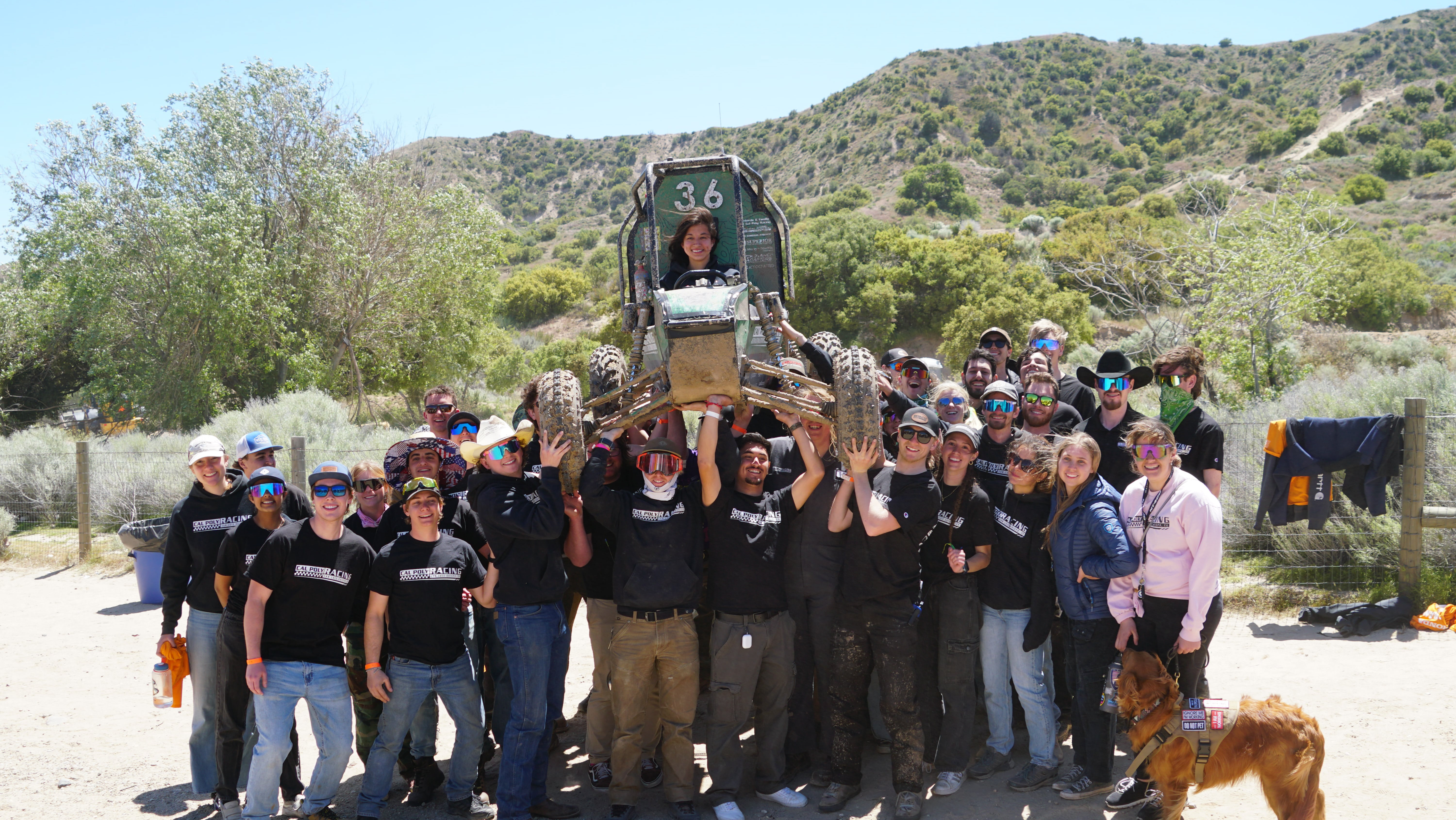
During the competition, our team secured 3rd place with a fastest run time of 2.7 seconds. That performance is shown in the video below.
In hindsight, some design decisions could be improved. The 90-degree manifold bend, while compact, introduced unnecessary losses. A vertical jet could have preserved more usable head. A taller, narrower reservoir could have reduced friction by supporting more tubing. Additionally, switching to a metal axle could have improved bearing alignment and reduced variability in performance. The custom variable-ratio pulley, while innovative, did not yield a quantifiable benefit and might be replaced by simpler string orientation techniques in future iterations. Ultimately, the project was a valuable learning experience in fluid mechanics, rapid prototyping, and system optimization under constraints