Our team’s objective was to design a hydronic heating system for an elementary school in Nome, Alaska. We calculated the building’s heating load, selected appropriate radiators and piping, determined pump specifications, and evaluated heat losses throughout the system. The final design aimed to provide an efficient and cost-effective solution suited to the extreme cold of rural Alaska, incorporating components such as heat exchangers and a combined heat and power plant for district heating.
__________________________________________________________________________________________

Ai Generated image of the school in nome.
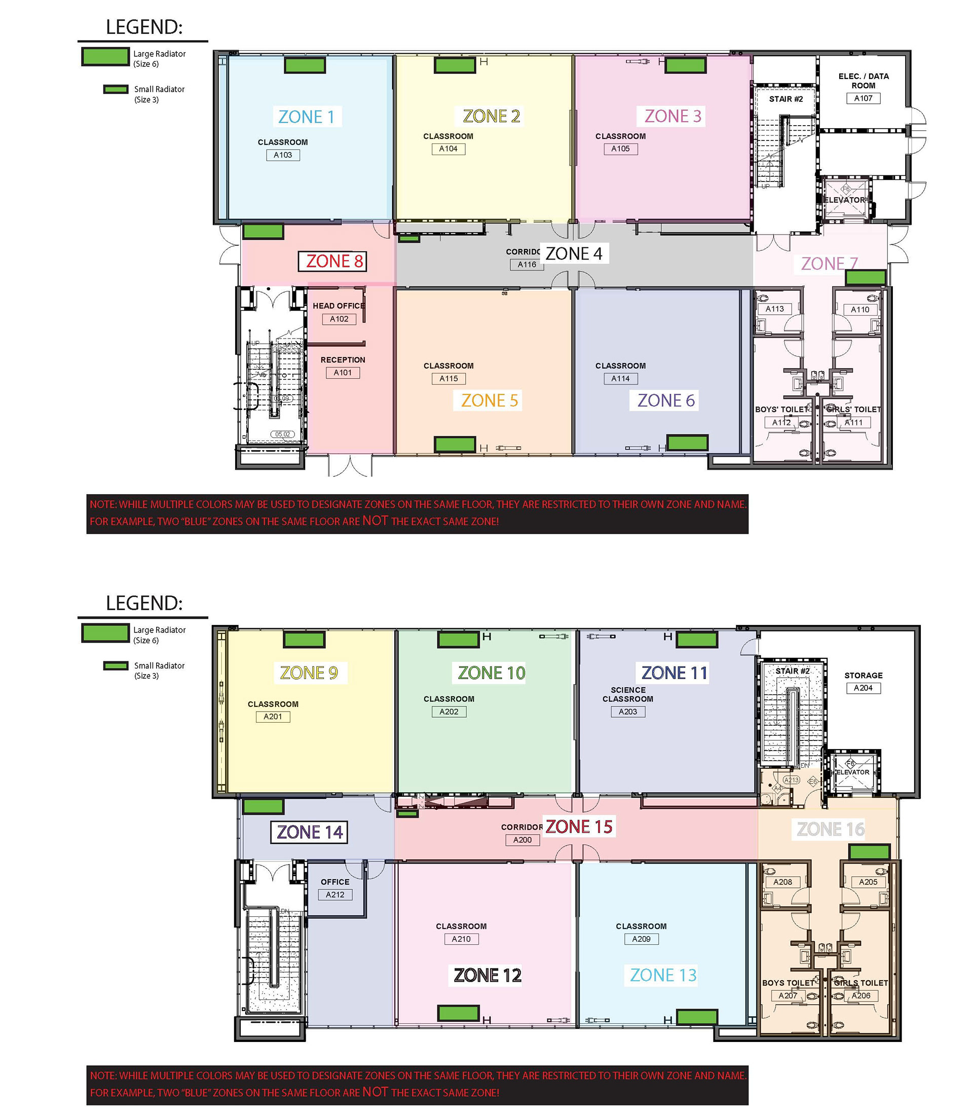
We were given the floor plan and had to divide up each area into zones. We calculated the heating load for each room using room dimensions, insulation values (R-values), and infiltration rates. Using these heat loss estimates, we selected and placed appropriate Modine hot water cabinet radiators in each zone based on performance data. See the bottom of the page for Excel files.
We organized our work into two main deliverables: a clearly labeled floor plan showing zone boundaries and radiator placements for both floors, and a detailed spreadsheet including material selections, heat loss calculations, and radiator specifications. Our goal was to balance heating loads across zones while minimizing the number of unique radiator models.
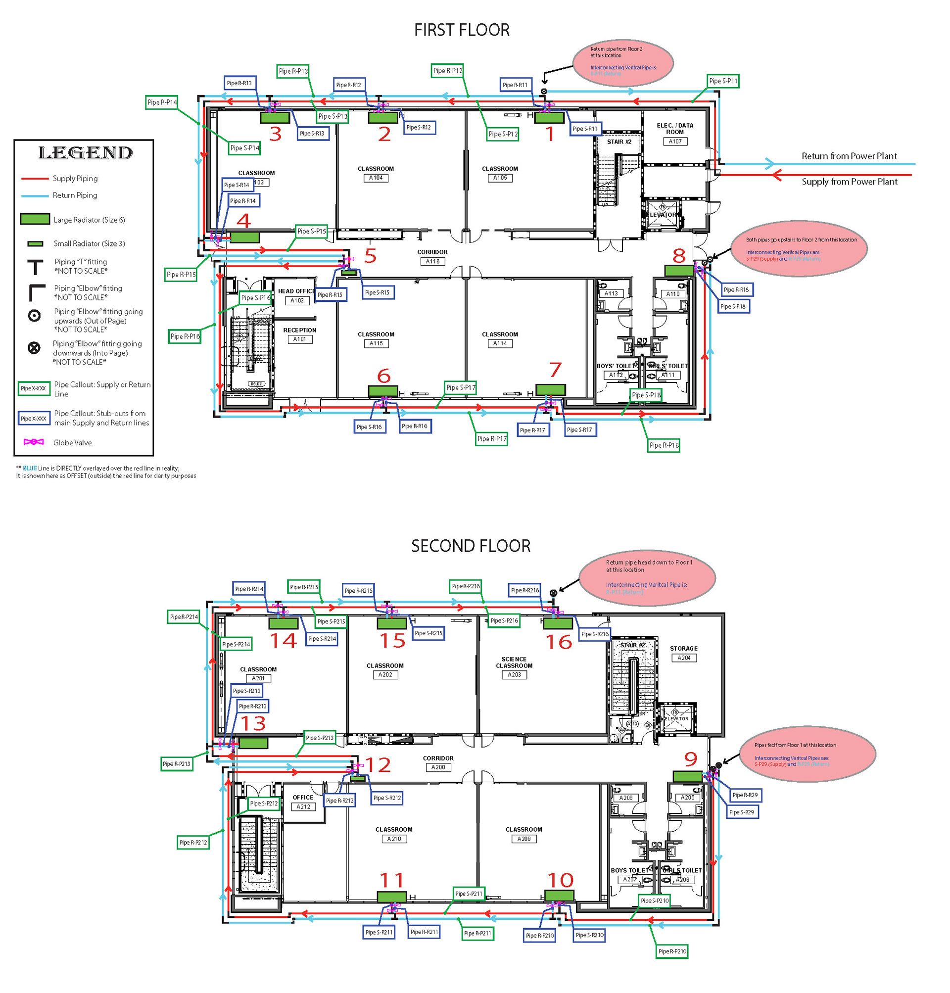
During Weeks 2 & 3, our team focused on designing the hot water piping system for the elementary school. We developed a parallel reverse-return layout to ensure equal flow and temperature distribution to all radiators. Using the provided floor plans, we sketched the piping network, identified all pipe segments, and calculated flow rates and velocities.
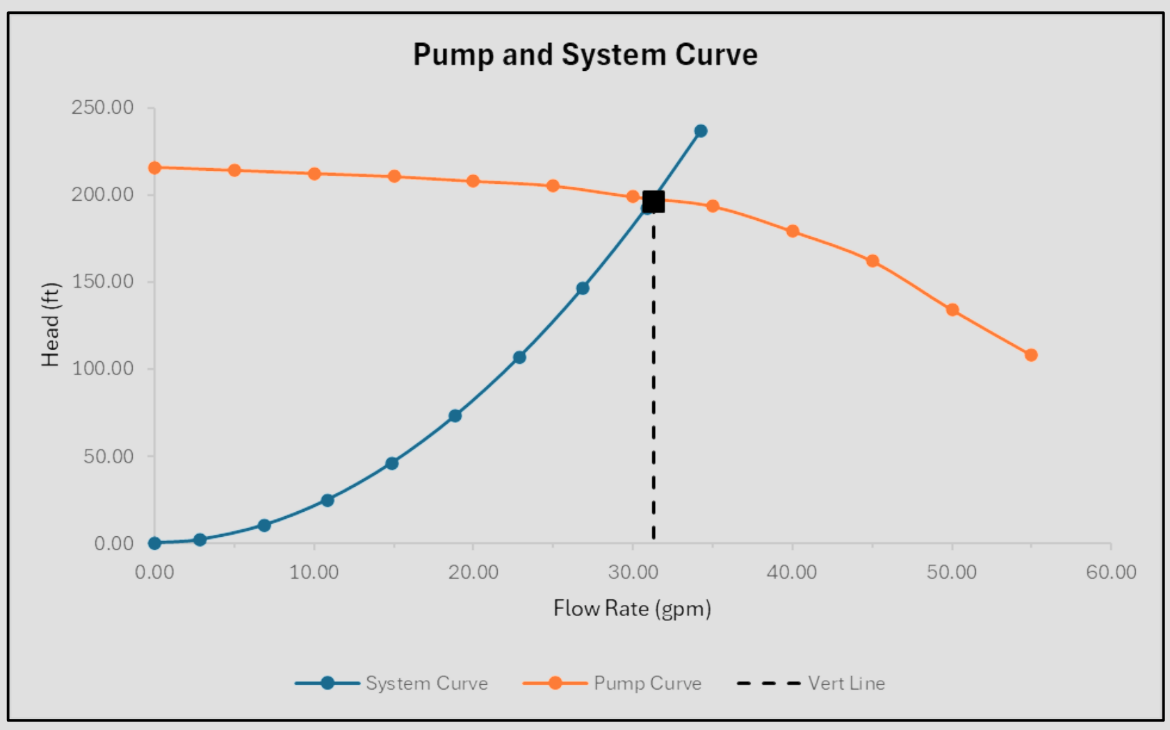
We selected Schedule 80 carbon steel piping and calculated both major and minor pressure losses using an Excel spreadsheet, incorporating fluid properties, fittings (elbows, tees, valves), and distances. For each radiator loop, we determined total head loss and identified the loop with the highest resistance to size the system pump accordingly. Finally, we created a system curve by varying flow rates and calculating corresponding head losses, which will be used in pump selection and system analysis.
In Weeks 4 & 5, our team focused on selecting and evaluating the circulation pump(s) needed for the hydronic heating system. Using the maximum head loss from our system curve, we selected an appropriate pump from the Grundfos catalog, ensuring it could meet the required flow rate and total pressure drop. We documented the selected pump’s model, size, BHP, quantity, and whether it was used in a series or parallel configuration.
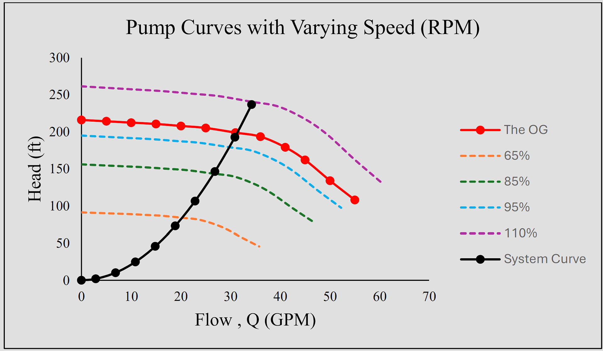
We then conducted a pump system study using pump affinity laws to simulate the performance of variable speed pumps at 65%, 85%, 95%, 100%, and 110% of nominal speed. This included plotting the modified pump curves alongside the system curve and identifying operating points at each speed. We created a table summarizing flow rate, head, efficiency, and BHP for each case, and discussed the potential benefits and trade-offs of using a variable frequency drive (VFD) in the final design.